Author: Auto Teach

  • How to Make a Bootable SD Card for Raspberry Pi

    This guide explains everything in simple words, step by step, so even someone who has never used
    Raspberry Pi before can follow it confidently.
    If you follow this guide carefully, your Raspberry Pi will boot successfully on the first try.

    1. What Is a Raspberry Pi?
      A Raspberry Pi is a small single-board computer. It does not have a built‑in hard disk like a laptop or PC.
      Instead, it uses a microSD card as its main storage.
      This SD card stores: – The operating system – System files – Your programs – Your data
      Without an SD card, Raspberry Pi cannot start.
    2. What Does “Bootable SD Card” Mean?
      A bootable SD card means: – It contains an operating system – The Raspberry Pi can read it – The Pi can
      start (boot) from it
      When power is supplied: 1. Raspberry Pi checks the SD card 2. Finds the boot files 3. Loads the
      operating system 4. Shows the desktop or terminal
      If the SD card is not bootable, you may see: – Red LED only – No display – Black screen
      1
    3. Things You Must Have (Very Important)
      Hardware Requirements
      You must have these items:
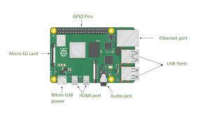
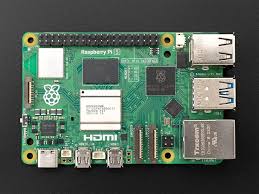
      Raspberry Pi Board (any model)
      Pi 3 / Pi 4 / Pi 5
      Pi Zero / Zero 2 W
      MicroSD Card
      Minimum: 16 GB
      Recommended: 32 GB or more
      Power Supply
      Use official or good quality adapter
      Low power causes boot failure
      SD Card Reader
      USB card reader or laptop slot
      Display & Cable (optional but helpful)
      HDMI cable
      Monitor or TV
    4. Choosing the Right SD Card (Do Not Ignore This)
      Bad SD cards cause 90% of Raspberry Pi boot problems.
      Recommended Specifications
      Speed: Class 10 / UHS‑1
      Brand: SanDisk, Samsung, Kingston
      Avoid unknown or fake cards
      Tip: If Raspberry Pi boots slowly or crashes, change the SD card first.
    5. Operating System for Raspberry Pi
      An operating system (OS) is required to control hardware and software.
      Best OS for Beginners
      Raspberry Pi OS (Official) – Stable – Easy to use – Full desktop support
      Available versions: – 32‑bit → Older models – 64‑bit → Newer models (Pi 4, Pi 5)
      Always choose Raspberry Pi OS with Desktop if you are new.
    6. Download Raspberry Pi Imager (Official Tool)
      Raspberry Pi Imager is the easiest and safest way to make a bootable SD card.
      It: – Downloads the OS automatically – Writes it correctly – Verifies files – Reduces errors
      Install it on: – Windows – macOS – Linux
    7. Insert SD Card into Computer
      Insert microSD card into card reader
      Connect card reader to computer
      Ensure the card is detected
      Backup data if needed
      Warning: SD card will be fully erased.
    8. Open Raspberry Pi Imager (Understanding the Screen)
      When you open the software, you will see three buttons:
      Choose Device → Select Raspberry Pi model
      Choose OS → Select operating system
      Choose Storage → Select SD card
      These steps prevent mistakes.
    9. Select Raspberry Pi Model
      Click Choose Device and select your model.
      Why this matters: – Correct boot files – Correct kernel – Best compatibility
      Example: – Raspberry Pi 4 – Raspberry Pi Zero 2 W
    10. Select Operating System (Detailed Explanation)
      Click Choose OS.
      Recommended options:
      Raspberry Pi OS (64‑bit) → Best performance
      Raspberry Pi OS (32‑bit) → Stable, older models
      Other OS options (advanced users): – Ubuntu – LibreELEC – RetroPie
      Beginner rule: Stick to Raspberry Pi OS.
    11. Select Storage Carefully
      Click Choose Storage and select your SD card.
      IMPORTANT: – Selecting the wrong drive can erase your hard disk – Always double‑check size and
      name
    12. Advanced Settings (EXTREMELY IMPORTANT)
      Press: – CTRL + SHIFT + X (Windows/Linux) – CMD + SHIFT + X (macOS)
      Configure Before Writing
      You can set:
      Username & password
      Enable SSH (remote access)
      Configure Wi‑Fi
      Time zone
      Keyboard layout
      Hostname
      This saves a lot of time later.
    13. Writing the OS to SD Card
      Click Write
      Confirm erase warning
      Wait patiently (5–10 minutes)
      Verification will run automatically
      Do not remove the SD card during writing.
    14. Safely Remove SD Card
      After completion: – Click eject – Remove SD card safely
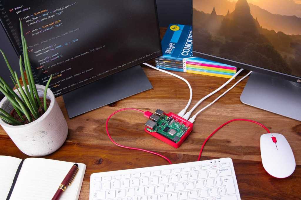
      Removing it unsafely can corrupt files.
    15. Booting the Raspberry Pi (First Time)
      Insert SD card into Raspberry Pi
      Connect HDMI
      Connect keyboard & mouse
      Plug power supply
      The Raspberry Pi will: – Show boot screen – Load OS – Display desktop or terminal
      Congratulations! Your Pi is running.
    16. First Boot Setup Explained
      On first boot: – Language selection – Country & Wi‑Fi – Password confirmation – Software update
      Let updates finish for best stability.
    17. Common Problems & Easy Fixes
      Problem: No Display
      Try HDMI port 0
      Check power adapter
      Re‑flash SD card
      Problem: Red Light Only
      Bad SD card
      OS not written properly
      Problem: Slow Boot
      Low‑quality SD card
      Use faster card
    18. Best Practices (Very Useful Tips)
      Always shut down properly
      Keep backups
      Use official power supply
      Keep OS updated
    19. Frequently Asked Questions (FAQ – SEO Boost)
      Q1. How do I make a bootable SD card for Raspberry Pi?
      You can make a bootable SD card for Raspberry Pi by using Raspberry Pi Imager, selecting your Pi
      model, choosing Raspberry Pi OS, and writing it to a microSD card.
      Q2. Which SD card is best for Raspberry Pi?
      A Class 10 or UHS‑1 microSD card from brands like SanDisk or Samsung (32GB or higher) is best for
      Raspberry Pi.
      Q3. Why is my Raspberry Pi not booting from SD card?
      Common reasons include a corrupted SD card, low‑quality power supply, wrong OS image, or improper
      flashing.
      Q4. Can I install Raspberry Pi OS without a monitor?
      Yes. Enable SSH and Wi‑Fi using advanced settings in Raspberry Pi Imager for headless setup.
      Q5. Is Raspberry Pi OS free?
      Yes, Raspberry Pi OS is completely free and officially supported.
    20. Final Words (Conclusion – SEO Friendly)
      Making a bootable SD card for Raspberry Pi is the first and most important step to start your
      Raspberry Pi journey. By using the official Raspberry Pi Imager, selecting the correct OS, and using a
      good‑quality SD card, you can avoid most boot problems.
      This step‑by‑step Raspberry Pi bootable SD card guide is designed for beginners, students, and
      hobbyists who want a clear and reliable method.
      Once your Raspberry Pi is running, you can explore programming, Linux learning, home automation,
      servers, robotics, and IoT projects.
      With the right setup, Raspberry Pi becomes a powerful learning and development tool.
      SEO Tip: Keep this article updated, add images with alt text like “Raspberry Pi bootable SD card setup”,
      and interlink related Raspberry Pi tutorials for higher Google ranking.
      Making a bootable SD card for Raspberry Pi is easy when done correctly.

      Once your Raspberry Pi is ready, you can use it for: – Programming – Home automation – Servers –
      Learning Linux – Robotics & IoT
  • Advanced Cybersecurity — Threat Models, Zero Trust, Detection, and Incident Response

    Advanced Cybersecurity — Threat Models, Zero Trust, Detection, and Incident Response

    A technical guide: modelling adversaries, designing zero-trust networks, telemetry & detection strategies (SIEM/XDR), and operational incident response processes.

    Cybersecurity defenseSecurity operations and defense-in-depth illustration (stock photo)

    Threat Modeling

    Systematically identify assets, entry points, trust boundaries, and likely adversary capabilities. Techniques: STRIDE, DREAD, and attack-surface analysis. Threat models inform mitigation priorities and logging requirements.

    Zero Trust Architecture

    Zero trust enforces never trust, always verify with strong identity, device posture checks, microsegmentation, policy-based access, continuous authentication, and encrypted transport (mTLS).

    Detection & Telemetry

    Collect high-fidelity telemetry: endpoint EDR events, network flows (NetFlow/IPFIX), process trees, DNS logs, and cloud audit trails. SIEM/XDR correlates events with detection rules and ML-based anomaly detection. Playbooks and SOAR automate triage.

    Incident Response

    IR lifecycle: preparation, identification, containment, eradication, recovery, and post-incident review. Forensic readiness (WORM logs, chain-of-custody) and tabletop exercises are essential. Purple teaming aligns red/blue to improve detection.

    References

    1. NIST SP 800-series, MITRE ATT&CK framework, SANS incident response materials.
    © 2025 Your Website Name


  • DevOps & CI/CD — Pipelines, Infrastructure as Code, Observability, and Release Strategies

    DevOps & CI/CD — Pipelines, Infrastructure as Code, Observability, and Release Strategies

    Technical summary of modern DevOps: pipeline design, IaC/GitOps, observability pillars, SRE principles, and safe release patterns.

    CI CD pipelineAutomated pipeline and infrastructure illustration (stock photo)

    CI/CD Pipelines

    Pipelines automate build, test, security scanning, and deployment. Key stages: source → build → unit/integration tests → container/image build → vulnerability scanning → deploy → smoke tests → promote. Artifacts must be immutable and signed.

    Infrastructure as Code & GitOps

    IaC (Terraform, CloudFormation) codifies infra. GitOps operates on the principle that the desired state is stored in Git and controllers reconcile cluster state (Flux, ArgoCD). Benefits include auditability, rollbacks, and declarative drift detection.

    Observability & SRE

    Observability comprises metrics, logs, and traces. SRE defines SLOs/SLIs, error budgets, and incident response. Practices include canary analysis, chaos engineering, and automated remediation.

    Release Strategies

    • Blue/Green: run two environments and switch traffic.
    • Canary: gradually shift traffic and monitor metrics.
    • Feature flags: toggle functionality without redeploying.

    References

    1. Fowler et al., CI/CD best practices; HashiCorp/Terraform docs; CNCF / GitOps resources.
    © 2025 Your Website Name


  • Computer Vision — Image Representations, CNNs, Detection, Segmentation, and Metrics

    Computer Vision — Image Representations, CNNs, Detection, Segmentation, and Metrics

    A concise technical overview of modern computer vision architectures and evaluation methodologies, plus deployment considerations for edge and cloud inference.

    Computer vision conceptFeature extraction and learned representations power modern vision systems.

    Image Representations & Preprocessing

    Images are tensors (H×W×C). Preprocessing: normalization, resizing, augmentation (flip, crop, color jitter). Feature extractors learn hierarchical representations from edges to semantic concepts.

    Convolutional Neural Networks

    Convolutions, pooling/strided convs, residual connections (ResNet), and depthwise separable convolutions (MobileNet) form the backbone of vision models. Transfer learning with pretrained backbones is standard.

    Detection & Segmentation

    Detectors: two-stage (Faster R-CNN) vs single-shot (YOLO/SSD). Segmentation: semantic (FCN, DeepLab), instance (Mask R-CNN), and panoptic segmentation (unified). Key trade-offs: speed vs accuracy, anchor-based vs anchor-free paradigms.

    Input Image
    Backbone (CNN)
    Head (Boxes, Masks)
    Typical detection pipeline: feature extraction followed by task-specific heads.

    Evaluation Metrics

    Classification: accuracy, F1; detection: mAP (mean Average Precision) at IoU thresholds; segmentation: IoU / Dice. Consider calibration and per-class analysis for imbalanced datasets.

    Deployment

    Edge inference uses quantization, pruning, and hardware accelerators (VPU, NPU). Cloud inference supports large models and batching. Real-time video analytics requires pipeline optimizations and batching strategies to meet FPS and latency targets.

    References

    1. He et al., “Deep Residual Learning for Image Recognition” (ResNet)
    2. Ren et al., “Faster R-CNN”
    3. Lin et al., “Focal Loss for Dense Object Detection” (RetinaNet)
    © 2025 Your Website Name


  • Natural Language Processing (NLP) — Models, Embeddings, Transformers, and Evaluation

    Natural Language Processing (NLP) — Models, Embeddings, Transformers, and Evaluation

    Technical survey of modern NLP: subword tokenization, embeddings, sequence models, transformer architectures, pretraining/fine-tuning, evaluation metrics, and deployment patterns.

    NLP concept illustrationSymbolic representation of language models and embeddings (stock image)

    Foundational Components

    Tokenization: Byte-Pair Encoding (BPE), WordPiece, and SentencePiece produce subword units balancing vocabulary size and OOV handling.

    Embeddings: Context-free (word2vec, GloVe) vs. contextual embeddings (ELMo, BERT) where vector representations vary with sentence context.

    Transformer Architecture

    Self-attention computes pairwise token interactions with scaled dot-product attention. Transformers stack encoder/decoder layers, using multi-head attention and feed-forward blocks with layer normalization and residual connections. Pretraining objectives include masked language modeling and next-token prediction.

    Input Tokens
    Q
    K
    V
    softmax(QKᵀ/√d)
    Weighted Sum · V → Output
    Scaled dot-product attention computes context-aware token representations.

    Training Paradigms

    Pretrain on large corpora (self-supervised) and fine-tune on downstream tasks. Transfer learning dominates—foundation models are adapted to classification, QA, summarization, and generation.

    Evaluation Metrics & Safety

    Metrics: accuracy, F1, BLEU/ROUGE (generation), perplexity (language modeling). Safety: toxicity detection, calibration, prompt robustness, and alignment considerations when deploying generative models.

    Deployment

    Serving strategies: server-side large model inference with batching and TPU/GPU acceleration; edge/quantized models for on-device inference. Retrieval-augmented generation (RAG) combines retrieval with generative models for up-to-date knowledge.

    References

    1. Vaswani et al., “Attention Is All You Need,” NeurIPS 2017.
    2. Devlin et al., “BERT: Pre-training of Deep Bidirectional Transformers,” 2019.
    3. Radford et al., OpenAI GPT series papers.
    © 2025 Your Website Name


  • Augmented Reality (AR) & Virtual Reality (VR) — Systems, Rendering, Tracking, and Use Cases

    Augmented Reality (AR) & Virtual Reality (VR) — Systems, Rendering, Tracking, and Use Cases

    Technical survey of AR/VR hardware, tracking and SLAM, rendering pipelines (latency & foveation), interaction models, and deployment considerations.

    AR VR HeadsetHeadset display systems and mixed-reality imagery (example stock photo)

    System Components

    AR/VR systems combine optics (HMD lenses, pancake or Fresnel), displays (OLED/LCD/LCOS), low-latency graphics pipelines, inertial and optical tracking, audio rendering, and input devices (hand controllers, hand-tracking, eye-tracking).

    Tracking & SLAM for AR

    AR requires robust 6-DoF tracking. Visual–inertial odometry (VIO) fuses IMU measurements with camera frames. SLAM systems (feature-based or direct) build local maps; loop-closure reduces drift. Key metrics: pose latency, pose jitter, and tracking robustness under dynamic lighting.

    IMU (High-rate)
    Camera Frames (30–90 Hz)
    VIO / SLAM
    Sensor fusion → pose
    Visual–inertial odometry fuses IMU and camera frames to produce low-latency pose estimates used for registration and rendering.

    Rendering Pipeline & Latency

    Motion-to-photon latency is critical; techniques include asynchronous reprojection, late latching, foveated rendering with eye tracking, and multi-resolution shading (tiled rendering). For distributed AR, network latency and synchronization are additional constraints.

    Interaction Models

    Interactions range from device-based controllers to direct hand/gesture and gaze. Haptics and audio spatialization enhance presence. UX constraints: minimizing simulator sickness, maintaining stable world-locked anchors, and ensuring comfortable ergonomics.

    Applications & Deployment

    • Enterprise training and remote assistance (AR overlays).
    • Industrial visualization, maintenance, and design review.
    • Immersive entertainment, VR simulation, and social VR.
    • Medical simulation and telesurgery assistance (requires deterministic low-latency networks).

    References

    1. SLAM and VIO literature; SIGGRAPH and IEEE VR proceedings for rendering and human factors.
    2. ETSI/3GPP for MEC/low-latency networking enabling AR/VR at the edge.
    © 2025 Your Website Name


  • Robotics & Autonomous Systems — Perception, Planning, Control, and SLAM

    Robotics & Autonomous Systems — Perception, Planning, Control, and SLAM

    A technical overview of modern robotics: sensor modalities, perception pipelines, simultaneous localization and mapping (SLAM), motion planning, control loops, autonomy stacks, ROS, and verification & safety.

    Sensing & Perception

    Robots integrate IMUs, LiDAR, cameras, RGB-D sensors, and proprioceptive encoders. Sensor fusion (EKF/UKF, factor graphs) produces robust state estimates for localization and mapping.

    SLAM and Mapping

    SLAM constructs a map while simultaneously estimating robot pose. Approaches include EKF-SLAM, Graph-SLAM (pose graph optimization), and particle-filter based methods; modern systems use lidar/camera fusion and loop-closure detection using bag-of-words or learned embeddings.

    Sensors (LiDAR, Camera, IMU)
    State Estimator / SLAM
    Map & Trajectory
    SLAM pipeline fuses raw sensor data into consistent maps and pose graphs.

    Motion Planning & Control

    Planning algorithms produce collision-free trajectories: sampling-based (RRT*, PRM), optimization-based (CHOMP, TrajOpt), and search-based methods. Controls implement tracking via PID, LQR, model predictive control (MPC), or adaptive controllers for dynamic tasks.

    Autonomy Stack & ROS

    Robotic stacks include perception, state estimation, planning, control, and behavior layers. ROS/ROS2 provide middleware for messaging, componentization, and simulation (Gazebo, Ignition). Verification and safety require simulation-in-the-loop, formal methods for critical behaviors, and runtime monitors.

    Applications

    • Autonomous vehicles and ADAS
    • Logistics and warehouse automation
    • Inspection drones and industrial robotics
    • Assistive robots and teleoperation

    References

    1. S. Thrun, W. Burgard, D. Fox, Probabilistic Robotics, MIT Press, 2005.
    2. O. Khatib et al., ROS/ROS2 documentation and community tutorials.
    © 2025 Your Website Name


  • Kubernetes & Container Orchestration — Architecture, Scheduling, Services, and Patterns

    Kubernetes & Container Orchestration — Architecture, Scheduling, Services, and Patterns

    A technical overview of container runtimes, Kubernetes control plane, scheduling algorithms, networking models, storage integration, Operators, and cloud-native design patterns.

    Containers and Runtimes

    Containers package an application and its dependencies in a lightweight, portable unit. Runtimes include containerd, CRI-O; OCI defines image format and runtime specs.

    Kubernetes Control Plane

    Key components: API server, etcd (cluster state), controller manager, scheduler, kubelet on nodes. The scheduler maps Pods to nodes based on resource requests, affinity/anti-affinity, and taints/tolerations.

    Control Plane (API, Scheduler, Controller)
    Worker Nodes (kubelet, container runtime)
    Simplified control-plane to node relationship; etcd provides consistent state storage.

    Networking & Service Discovery

    Kubernetes uses Services (ClusterIP, NodePort, LoadBalancer) and DNS for discovery. CNI plugins (Calico, Flannel, Weave) implement pod networking. Service meshes (Istio, Linkerd) provide mTLS, observability, and traffic control.

    Storage and Stateful Workloads

    PersistentVolumes and CSI drivers expose block and file storage to pods. Patterns: StatefulSets for stable network IDs and ordered startup, Operators for lifecycle management of complex systems (databases, message queues).

    Scheduling & Autoscaling

    Autoscaling: HPA (horizontal pod autoscaler), VPA (vertical pod autoscaler), and Cluster Autoscaler. Scheduling policies consider resource bin-packing, topology, and custom scheduler extensions.

    References

    1. Kubernetes documentation, CNCF resources, and CNCF whitepapers on operators and cloud-native patterns.
    © 2025 Your Website Name


  • Internet of Things (IoT) — Architecture, Protocols, Security, and Applications

    Internet of Things (IoT) — Architecture, Protocols, Security, and Applications

    A technical survey of IoT device classes, connectivity stacks, edge and cloud interactions, telemetry pipelines, device management, security practices, and industry use cases.

    IoT Architecture Overview

    IoT systems commonly follow a layered architecture: Devices & sensors → Edge gateways → Connectivity networks → Cloud backends → Analytics & applications. Real-time constraints, intermittent connectivity, and device heterogeneity drive design choices.

    Connectivity & Protocols

    • MQTT: Lightweight pub/sub for telemetry over TCP/TLS.
    • CoAP: Constrained REST over UDP for low-power devices.
    • LoRaWAN: Low-power wide-area network for long-range sensor telemetry.
    • Bluetooth Low Energy / Zigbee: Short-range mesh/local connectivity.
    Sensors
    Gateways
    Network
    Cloud / Analytics
    Typical telemetry path from sensors to cloud analytics with edge gateways for preprocessing and protocol translation.

    Device Management & Security

    Device lifecycle functions: provisioning, OTA updates, health telemetry, and decommissioning. Security: hardware roots of trust (TPM), mutual TLS, secure boot, signed updates, and least-privilege access. Scale and heterogeneity make key management and fleet-wide policies critical.

    Data Pipelines & Edge Processing

    Edge processing reduces bandwidth by filtering, aggregating, and running inference locally. Telemetry pipelines include message ingestion, stream processing, time-series databases, and feature stores for ML.

    Representative Use Cases

    • Industrial IoT (predictive maintenance, digital twins)
    • Smart cities (traffic, utilities, public safety)
    • Healthcare (remote monitoring, asset tracking)
    • Retail (supply chain, cashierless stores)

    References

    1. IETF, OASIS, LoRa Alliance, IEEE and industry whitepapers on protocols and security best practices.
    © 2025 Your Website Name


  • 5G Technology — Architecture, Spectrum, RAN, Core, and Use Cases

    5G Technology — Architecture, Spectrum, RAN, Core, and Use Cases

    A concise technical overview of 5G New Radio (NR), spectrum considerations (sub-6 GHz and mmWave), the 5G Core (5GC), network slicing, MEC, and primary service classes.

    Overview & Service Classes

    5G targets three primary service categories: eMBB (enhanced Mobile Broadband), URLLC (Ultra-Reliable Low-Latency Communications), and mMTC (massive Machine Type Communications). These are accomplished through NR air interface flexibility, spectrum diversity, and a cloud-native 5G Core.

    RAN and Spectrum

    5G NR supports flexible numerologies, scalable OFDM, and beamforming. Spectrum is categorized as:

    • Low-band: <1 GHz — wide coverage, lower capacity.
    • Mid-band: ~1–6 GHz — balance of coverage and capacity.
    • mmWave: >24 GHz — very high capacity, limited range, requires dense small cells and beam steering.

    UE (Phones, CPE) gNodeB (gNB) / Small Cell 5G Core (5GC) Simplified path: UE ↔ gNodeB (RAN) ↔ 5G Core for session/state control and user plane.

    5G Core & Network Slicing

    5GC is cloud-native and service-based (SBA). Key functions include AMF (Access and Mobility), SMF (Session Management), UPF (User Plane Function), and PCF (Policy Control). Network slicing creates logically isolated networks tailored for latency, reliability, or throughput using orchestration and admission controls.

    Edge & MEC

    Multi-access Edge Computing (MEC) places compute and storage near the RAN to support low-latency services (AR/VR, gaming, V2X). Integration with 5GC enables local breakout and optimized routing.

    Use Cases and Challenges

    • eMBB: high-throughput consumer services (4K/8K streaming, fixed wireless access)
    • URLLC: industrial automation, remote surgery, autonomous driving
    • mMTC: IoT sensor networks, smart city deployments

    Challenges: densification costs for mmWave, spectrum allocation, power efficiency, and security across multi-stakeholder deployments (operators, verticals).

    References

    1. 3GPP TR and TS documents for NR and 5GC.
    2. ETSI MEC specifications.
    3. Technical whitepapers from major vendors and standards bodies.

    © 2025 Your Website Name

    5G Technology — Architecture, Spectrum, RAN, Core, and Use Cases

    A concise technical overview of 5G New Radio (NR), spectrum considerations (sub-6 GHz and mmWave), the 5G Core (5GC), network slicing, MEC, and primary service classes.

    Overview & Service Classes

    5G targets three primary service categories: eMBB (enhanced Mobile Broadband), URLLC (Ultra-Reliable Low-Latency Communications), and mMTC (massive Machine Type Communications). These are accomplished through NR air interface flexibility, spectrum diversity, and a cloud-native 5G Core.

    RAN and Spectrum

    5G NR supports flexible numerologies, scalable OFDM, and beamforming. Spectrum is categorized as:

    • Low-band: <1 GHz — wide coverage, lower capacity.
    • Mid-band: ~1–6 GHz — balance of coverage and capacity.
    • mmWave: >24 GHz — very high capacity, limited range, requires dense small cells and beam steering.

    UE (Phones, CPE)
    gNodeB (gNB) / Small Cell
    5G Core (5GC)
    Simplified path: UE ↔ gNodeB (RAN) ↔ 5G Core for session/state control and user plane.

    5G Core & Network Slicing

    5GC is cloud-native and service-based (SBA). Key functions include AMF (Access and Mobility), SMF (Session Management), UPF (User Plane Function), and PCF (Policy Control). Network slicing creates logically isolated networks tailored for latency, reliability, or throughput using orchestration and admission controls.

    Edge & MEC

    Multi-access Edge Computing (MEC) places compute and storage near the RAN to support low-latency services (AR/VR, gaming, V2X). Integration with 5GC enables local breakout and optimized routing.

    Use Cases and Challenges

    • eMBB: high-throughput consumer services (4K/8K streaming, fixed wireless access)
    • URLLC: industrial automation, remote surgery, autonomous driving
    • mMTC: IoT sensor networks, smart city deployments

    Challenges: densification costs for mmWave, spectrum allocation, power efficiency, and security across multi-stakeholder deployments (operators, verticals).

    References

    1. 3GPP TR and TS documents for NR and 5GC.
    2. ETSI MEC specifications.
    3. Technical whitepapers from major vendors and standards bodies.
    © 2025 Your Website Name